A construction equipment supplier of construction machinery solutions for 30 years. WhatsApp:+86-18968212829
Language
A construction equipment supplier of construction machinery solutions for 30 years. WhatsApp:+86-18968212829
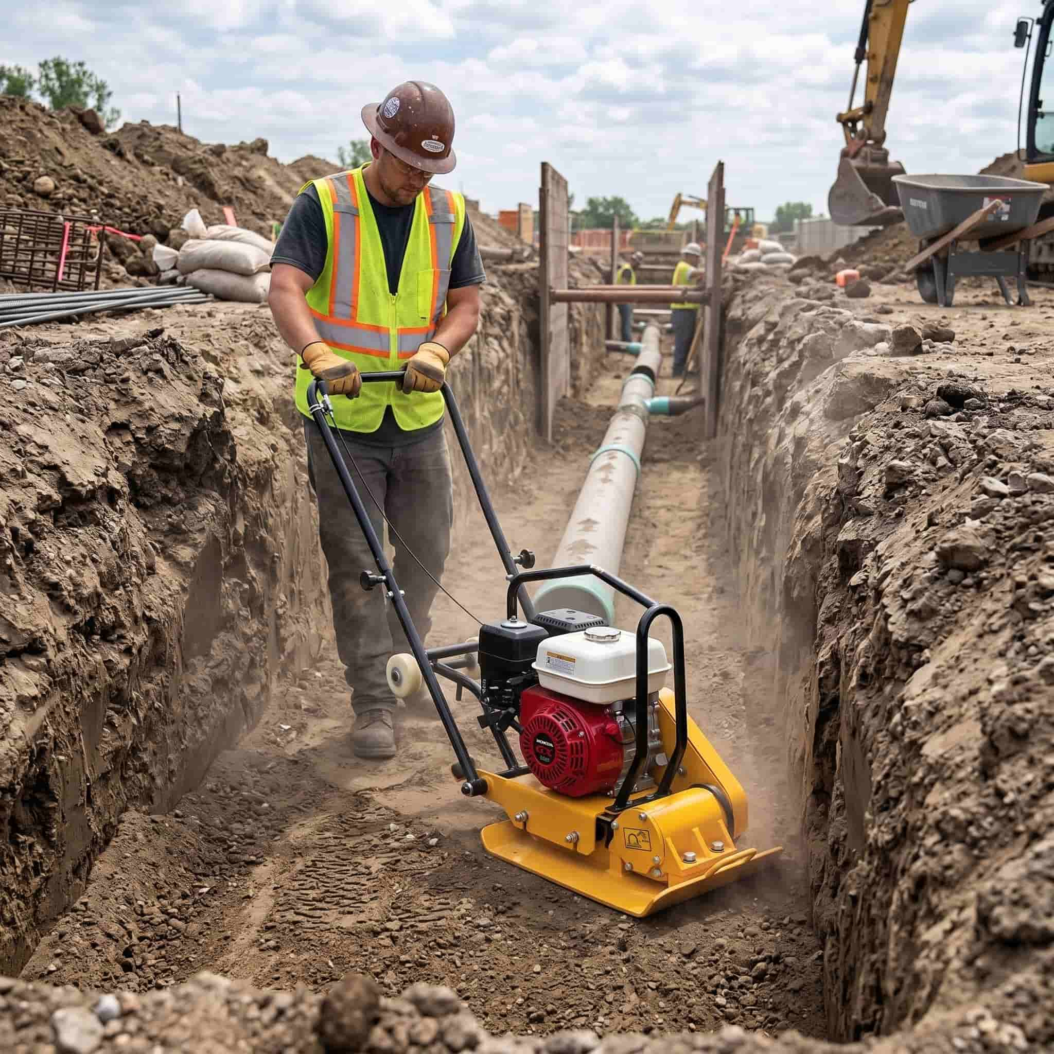
Here's a scenario that plays out on construction sites more often than anyone likes to admit: the trench is backfilled, the surface is restored, the crew packs up, and six months later a sinking strip appears along the exact line of the utility run. The pavement drops, the client calls, and suddenly everyone is trying to figure out whose fault it is. The honest answer, most of the time, is that nobody did anything dramatically wrong — they just treated backfill compaction as the final formality instead of the structural step it actually is. This guide exists to fix that thinking, because getting trench compaction right isn't difficult once you understand what's happening underground and why each step matters.
The two most common causes of post-trench settlement are bad fill material and inadequate compaction. Bad fill is easy to spot and usually gets caught early. Inadequate compaction is sneakier — the surface can feel completely solid while a poorly compacted zone sits two feet below grade, quietly waiting for traffic load or a wet season to trigger the drop. When it goes, it doesn't go all at once. It sags gradually in that telltale strip that follows the trench line perfectly, which is how inspectors know exactly what they're looking at.
The second failure mode is less visible but structurally more serious. Flexible pipes — PVC, HDPE, corrugated steel — rely on the surrounding soil to provide lateral support. When the material around the pipe isn't properly compacted, the pipe deforms under vertical load. Its cross-section shifts from round to oval, wall stress builds up, and over time the pipe fails well ahead of its design life. You won't see this one until a camera inspection or, worse, a collapse. Either outcome involves a difficult conversation and an expensive excavation.
The single most useful mental shift in trench backfill work is to stop thinking of the trench as one big hole to fill and start thinking of it as three distinct zones stacked on top of each other. Each zone has different structural responsibilities, different compaction requirements, and in some cases, different equipment. Treating them all the same is where most compaction problems begin.
The bedding layer sits directly under the pipe — typically 4 to 6 inches of carefully placed material that gives the pipe a uniform, load-distributing surface to rest on. This zone doesn't get compacted with power equipment. It gets hand-placed and lightly tamped, because what you're trying to avoid is point loading under the pipe barrel. The haunching material, which fills in from the bedding up to the pipe's centreline on both sides, is the lateral support zone — arguably the most structurally critical section of the entire trench. Work here with a lightweight rammer kept at least 12 inches from the pipe wall, compacting carefully without generating impact forces that could shift the pipe or damage its joints. Take your time in this zone. Everything above it depends on it being done right.
From roughly 12 inches above the pipe top to about 18 inches below the finished surface is where the compaction effort really lives. Most project specifications require 95% of Standard Proctor density (ASTM D698) through this zone for road crossings, and that number means something specific — it can't be eyeballed or estimated by feel. This is where a tamping rammer earns its place, especially in narrow trenches backfilled with cohesive native soil. Its narrow baseplate fits alongside the pipe without drama, its impact energy penetrates vertically through each lift, and it works on clay-dominant fill in a way that vibration-based machines simply can't match. If you've ever wondered why equipment selection matters so much in trench work specifically, this is the zone that explains it. For a full breakdown of when a rammer outperforms a plate compactor — and when it doesn't — [our guide on Rammer vs. Compactor: Unveiling the Key Differences] covers the decision in detail.
The top section — the last 12 to 18 inches before the sub-base or pavement layer — is where conditions finally open up enough to bring in a plate compactor, particularly if the trench width allows it and the fill transitions to imported granular material or road base aggregate. Speed and surface coverage become more useful here than deep impact penetration. Two perpendicular passes with a reversible plate compactor across the final lift is the standard minimum. Don't shortcut this zone just because it's close to the surface — it takes the most direct traffic load, and it's the layer that shows settlement first.
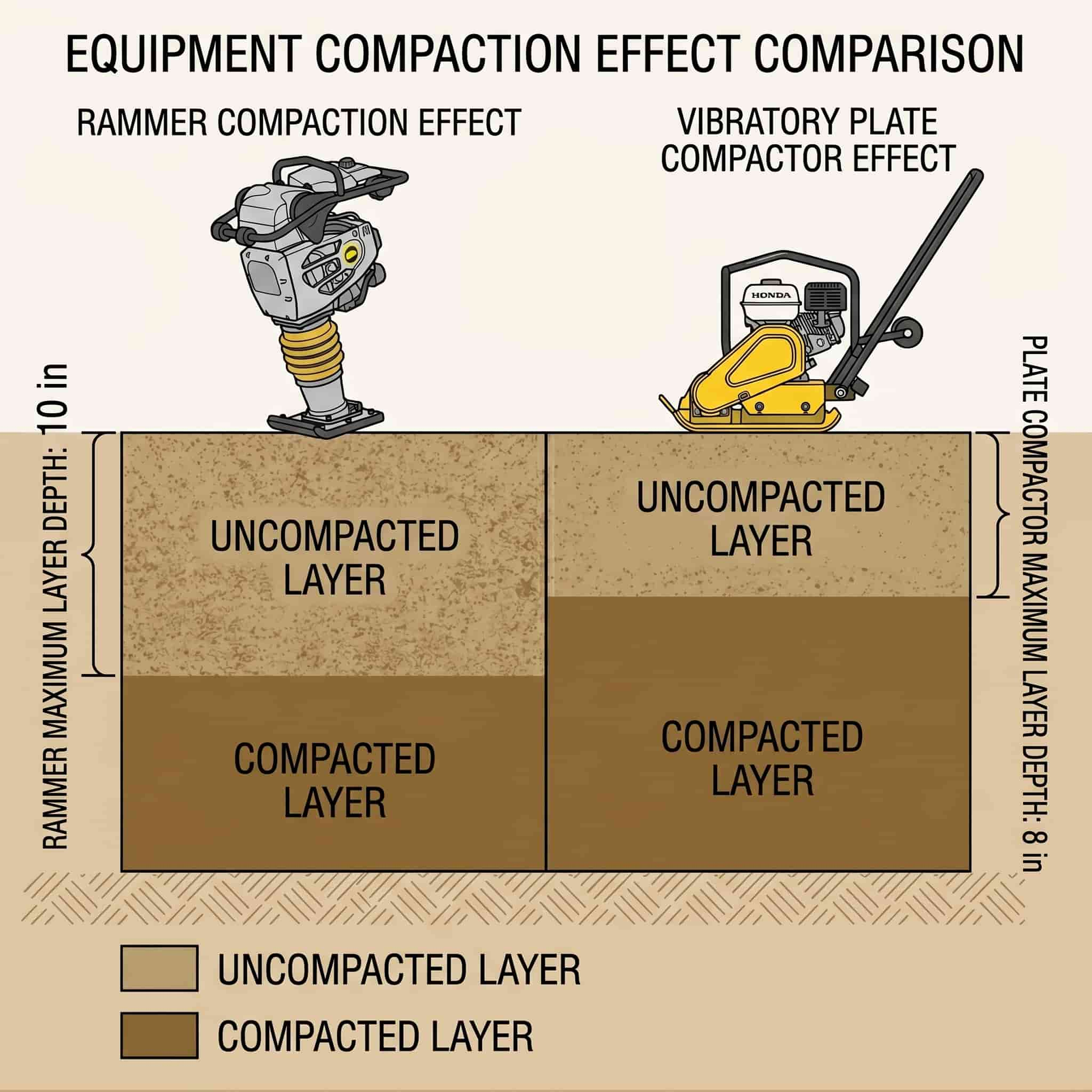
If there's one rule that separates crews who rarely fail compaction tests from crews who fail them regularly, it's this: work in thin lifts and count every pass. A rammer working on cohesive fill should be operating on no more than 8 to 10 inches of loose material per lift. A plate compactor on granular fill tops out at 6 to 8 inches per lift under most site conditions. Trying to compact a 14-inch lift in one go produces a reliable illusion — the surface firms up, everything looks good, and the bottom half of the lift hasn't been touched by meaningful compaction energy. That uncompacted layer is the settlement waiting to happen.
Pass count isn't just a formality either. The baseline for most specification-compliant trench work is two overlapping passes per lift with a rammer, or two perpendicular passes with a plate compactor. Near road crossings with clay-heavy native fill, three passes is a more defensible baseline. Beyond that, additional passes yield diminishing returns once the material reaches its Proctor optimum — and pushing past that point on cohesive soil can actually cause shear failure rather than further densification, which is the compaction equivalent of overtightening a bolt.
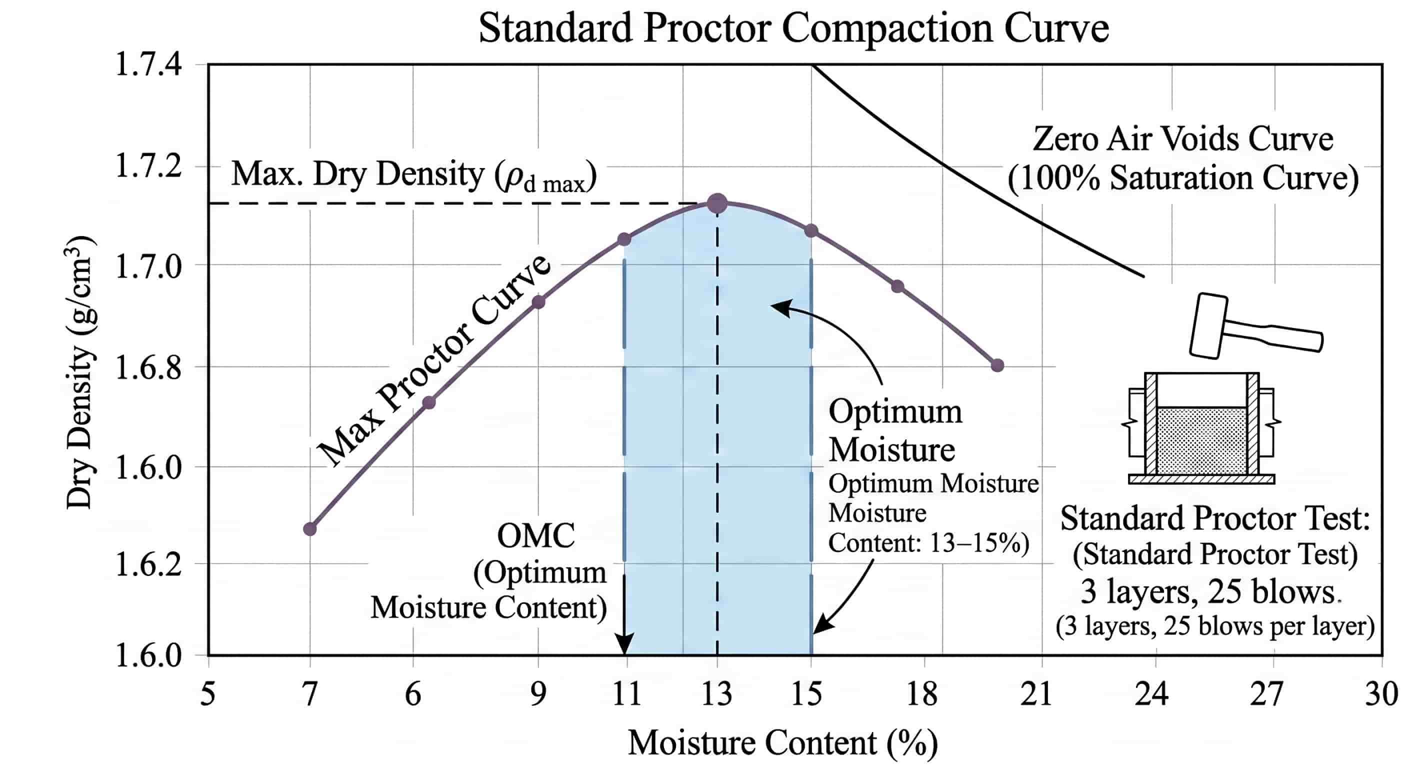
Soil compacts most efficiently at or near its optimum moisture content — typically around 13 to 15 percent for clay-dominant fill. Below that range, the soil particles resist rearrangement no matter how many passes the machine makes. Above it, the fill goes plastic and pushes sideways instead of densifying downward, which is also one of the ways pipes get displaced. In practice, this means checking fill moisture before the first lift goes in, especially when you're using excavated native material that has been sitting in a spoil pile through variable weather. Visibly wet, sticky fill needs time to drain or should be aerated by spreading and turning before compaction starts. Adding more passes to wet fill is not a substitute for waiting — it just wastes time and fuel while the soil laughs at the machine.
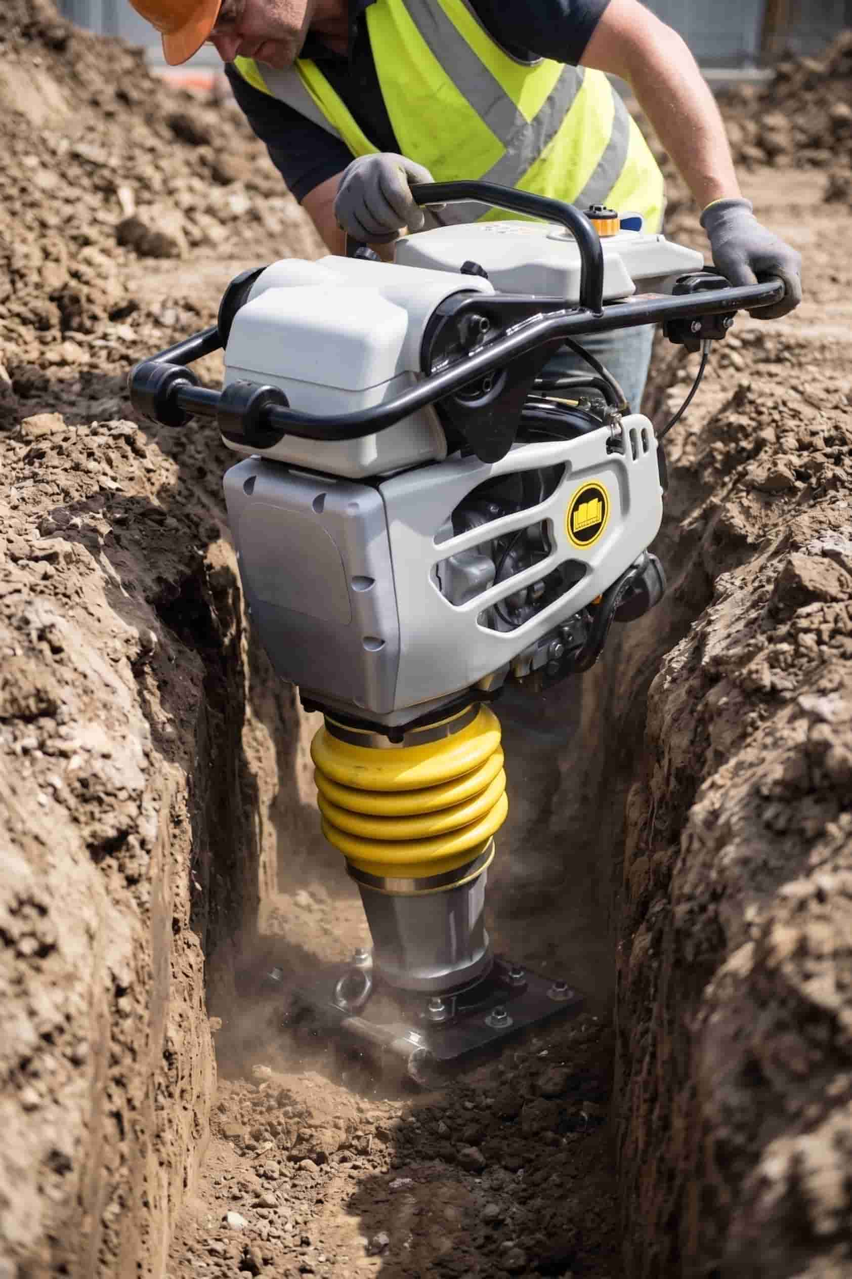
Trench geometry eliminates most compaction equipment before you even get to a soil type discussion. Standard utility trenches run 18 to 36 inches wide, and with a pipe sitting in the centre, working clearance is limited. A plate compactor is too wide for most of these conditions and has no way to get around pipe joints or fittings without risking damage. The rammer's narrow baseplate — 11 to 13 inches on most models — fits comfortably alongside the pipe zone, and the upright operating stance means the machine can be managed from the trench edge without putting the operator in the excavation.
On clay-dominant native fill, which is the most common scenario in urban utility trenching, the rammer's percussive impact is also the right physical tool for the material. Clay particles bond through surface chemistry, not friction, and they don't respond meaningfully to vibration. They need direct impact force to release trapped air and water from the soil matrix. This is exactly what a rammer delivers — and exactly what a plate compactor cannot reliably provide in cohesive material.
Feeling the ground with your boot is not a compaction test. It's a guess. The two field methods that actually go on the project record are the nuclear density gauge (ASTM D6938), which gives rapid density and moisture readings in-situ, and the sand cone test (ASTM D1556), which is slower but needs no calibrated equipment beyond basic site tools. Both express the result as a percentage of the Proctor maximum dry density. For the main backfill zone, most road and utility specs require 95% of Standard Proctor. Within the top 12 inches under pavement, 98% is the common requirement.
A practical testing cadence for road crossings is one density test per 100 linear feet of trench per lift, and one test per lift change on inspected work. If the test comes back below spec, run two more passes and retest before placing the next lift. Adding more fill over under-compacted material doesn't solve the problem — it buries it, and eventually the ground surface will find it for you.
Choosing the right compaction machine is the first decision, and getting it wrong affects everything that follows. For a clear breakdown of when to use a tamping rammer versus a plate compactor — including soil type, lift depth, site geometry, and cost — read our full guide: [Rammer vs. Compactor: Unveiling the Key Differences].

